
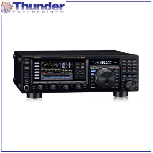
FT DX 3000
• General Coverage Reception from 30 kHz to 56 MHz
• FM & AM – Wide and Narrow modes included
• A Block Diagram Displays RX Signal Path
• Choose Analog Type or Bar Graph Meter
• Selectable analog type or bar graph type meter indication
• Separate Independent Frequency Display
• High Speed Spectrum Scope
• Bandwidth of the spectrum scope: 20kHz, 50kHz, 100kHz, 200kHz, 500kHz, or 1MHz
• TX and RX markers appear during “spit” operation
• Level Indicator
The function names and the setting levels of the following functions are shown in the TFT main display when a function knob is rotated: Clarifier, Microphone Gain, Speech Processor, SHIFT, WIDTH, KEYER SPEED and CONTOUR
• AF-FFT Scope
An AF-FFT (Audio Frequency Fast Fourier Transform) scope is built in. This AF-FFT function was first demonstrated in the FT DX 9000 series. With this Scope, the audio characteristics of the received signals; the effect of adjusting the RX IF filter performance; and utilizing the QRM rejection features, may be visually observed. It is also possible to observe the TX audio characteristics of your own signal while using the Monitor function. This is very effective for tuning the parametric equalizer for voice characteristics and the microphone audio.
• Spectrum Scope Memory
The Spectrum Scope screen can be stored or recalled with one touch. Simultaneously the time information is recorded in the memory, so that the difference in activity may be reviewed and compared, depending on the seasons and times.
• Cursor Keys
Six keys that are used frequently in normal operation are located at the left side of the TFT display. Other functions can be operated by pressing the “SCOPE” key which changes the “Spectrum Scope screen” to “Function Key Display screen”. Even if the radio is turned off, the last operated Key Function is memorized and highlighted.
• Fifteen separate band pass filters (BPF) are used for front end protection. This effectively reduces the undesired and out of band signals.
• In the RF amplifier, the strong bipolar transistor (2SC3357) is used. This transistor shows a low NF, and provides superior intermodulation performance.
• The gain of each individual device is kept lower, and the best optimized working point, with the lowest NF, is selected.
• A custom-designed wide coverage transformer, with less magnetic saturation, is used for the I/O of the RF amplifier. This construction makes the device performance better and provides excellent multi signal performance.
• The 3 kHz roofing filter greatly improves SSB signal reception during close adjacent multi signal conditions.
• The 300 Hz* and 600 Hz roofing filters provide the best CW receiving environment when the adjacent signals may affect the desired signal reception.
*Note: 300 Hz filter optional
• Proven IF WIDTH and IF SHIFT functions provide great QRM rejection performance
IF SHIFT
With the normal bandwidth, the pass band area can be moved relatively, so that harmful signals are rejected from the pass band
IF WIDTH
By adjusting the band width, Interfering signals can be removed from both sides of the pass band, without changing the pass band position. The IF width function can make the pass band narrower with one-touch. This function is effective in a pile-up or contest, when the undesired signals are located just above and below the target signal. When the IF Width knob is centered (click point), the pass band width is 2.4 kHz in the SSB and CW modes. When “NAR” is turned on, the minimum pass band becomes 50 Hz (200 Hz in the SSB mode), making it possible to minimize the QRM with this sharp filter shape factor. When the IF Width is turned clockwise from the center click point, the pass band width can be extended wider, up to 4000 Hz. This may provide a richer sounding and more comfortable QSO when in a local rag chew.
• CONTOUR
The CONTOUR function ideally tailors the received audio signal without changing the bandwidth. The CONTOUR function varies the outline of the IF DSP filter pass band characteristics, and the in-band signal construction can be partially altered. Different from the IF SHIFT or IF WIDTH, the special CONTOUR pass band, can reduce or peak the desired signal, partially and continuously across the pass band. This feature is effective especially when the undesired signal is close to the center frequency.
• Digital Noise Reduction (DNR) by DSP
The installed digital noise reduction circuit provides 15 separate parameters. The noise reduction constants may be set to the optimal working point by varying the 15 step parameters according to the actual noise within the HF band. The desired signal components are peaked and the random noise components are effectively cancelled.
• IF NOTCH
This high Q circuit has steep attenuation characteristics of 70dB or more. Effective removal of a strong beat signal is obtained. The damping characteristics can be switched to wide or narrow band width, and the attenuation level may be adjusted in the Setting Mode Menu. Interfering signals may be attenuated, while minimizing the impact on the received signal.
• Digital Notch Filter (DNF) (AUTO NOTCH)
The Digital Notch Filer (DNF) is a feature that automatically follows the interfering heterodyne signals, even if there are more than one, and even if the beat frequency changes with time. This is effective in removing jamming signals.
• CW APF (Audio Peak Filter)
In the CW mode, the APF (Audio Peak Filter) function has an audio peak at the signal frequency; this improves the S/N and increases the readability of the CW signal. The APF peak frequency can be finely aligned.
In the FT DX 3000, the combination of it’s high stability and high accuracy 40 MHz TCXO (± 0.5ppm, -10 °C ~ +60 °C), and it’s DDS create the fundamental frequency of this radio, and is locked to the PLL-IC and VCO directly. This circuit construction and method creates the highest quality local signal, with superior S/N performance. This means the receiver noise floor is kept lower, and realizes the best blocking dynamic range at 2 kHz IP3 performance.
The IPO (Intercept Point Optimization) is selected by a control switch located on the front panel. The IPO selection determines the gain of the RF amplifier. The gain setting is very effective in optimizing the receiver performance, depending on the antenna and the communication propagation conditions. The IPO, the ATT and one stage of the RF amplifier are used to optimize the signal levels that are sent to the mixer. This is especially important for HF low-band operation. The “AMP 1” uses one RF amplifier stage, and maintains a better balance between the sensitivity and the receiver performance (the gain is around 10 dB). In addition, “AMP 2” uses two stages of the RF amplification and can obtain higher sensitivity (the gain is around 17 dB); something particularly important on the 6 and 10 meter bands.
• Microphone Amplifier that includes Parametric Equalizer
The modulation circuit of the FT DX 3000 utilizes the digital variation operational modulation type, which creates ideal high quality transmission audio. This radio has a parametric equalizer that makes possible versatile adjustment of the TX audio quality by aligning the TX band audio spectrum. The parametric equalizer can alter the Low, Mid and High part of the audio separately. This three stage parametric equalizer can generate high quality TX audio sound because it can be tuned in detail…without sacrificing the audio dignity.
• IF DSP Speech Processor – DX’er and Contester Proven
The SSB Speech Processor uses IF digital signal processing to increase the intelligibility of the transmitted signal during weak signal crowded conditions. The DSP increases the average power of the important speech spectrum components and reduces the TX power of the less significant components. Adjust the compression level in the Menu Mode to adapt the transmitted SSB signal to best suite your voice characteristics, the situation, propagation conditions and pile-up demands.
• Having multiple antenna selections is an especially effective feature for DX and Contest operating.
• Antenna connection selections memorized and recalled when changing bands.
• The “ANT 3” input can be set for the “RX Only” antenna.
CW Features Galore• CW APF (Receiver Audio Peak Filter) with 3 bandwidth steps• CW Decode included
• CW SPOT
• CW Auto Zero-in
• CW Zero-in Display
• CW Full Break-in
• CW Mode reversal (USB or LSB)
• CW Keying available during SSB operation
• CW “VOX” Delay is adjustable
• Electronic Keyer with Weight control
• Keyer paddle Dot-Dash reversal
• IAMBIC A/B selection
• “Bug” Keying emulation
• Four Message Memory (50 characters each); five w/FH-2 Keypad
• Automatic Insertion of incrementing contest number
• Automatic “Beacon” keyer mode
• Dial step setting (for the CW mode only)
• Separate KEY Jacks on the front and rear panels
A large diameter 28 mm inductor, with an adjustable ferrite magnetic material (Ni-Zn ferrite) core, is combined, with a high resolution and high torque stepping motor to automatically find the resonance point. By inserting these tuning units prior to the RF front end of the receiver, the IP3 points are improved by around 4 dB. Three individual tuning units are available covering frequencies from 1.8 MHz through 14 MHz. Many FT 950, FT 2000/D, FT DX 5000 and FT DX 9000 Yaesu customers have used them and found them especially effective for use on the Lower Bands.
| Antennas | ||||
| FC-40 Antenna Tuner | Automatic Antenna Tuner (For Long Wire Antenna) |  |
||
| Cables | ||||
| CT-178 | Quadra Control Cable |  |
||
| CT-39 | Packet Cable | |||
| SCU-27 | Antenna Rotator Connection Cable | |||
| Filters | ||||
| XF-127CN | CW Narrow Crystal Filter | |||
| Headsets | ||||
| YH-77STA | Lightweight Stereo Headset for use with HF transcievers |  |
||
| Microphones | ||||
| M-1 | Reference Microphone |  |
||
| M-100 | Dual Element Microphone |  |
||
| MD-100A8X | Desktop Microphone |  |
||
| MD-200A8X | Desktop Microphone |  |
||
| Optional Boards | ||||
| DVS-6 | Voice Memory Unit |  |
||
| Power Supplies | ||||
| FP-1023 | Power Supply (23A) |  |
||
| FP-1030A | Power Supply (30A) |  |
||
| Speakers | ||||
| SP-20 | External Speaker |  |
||